Aeroengine Design Project
Summary:
- Aeroengine Design Mentor: Jim Hermanson
- Aeroengine Design project team: Felicity Cundiff and Angelina dos Remedios
- In our Airbreathing Propulsion project, we designed a gas turbine engine core, including a compressor, combustor, and turbine, focusing on optimizing performance and cost-efficiency. We utilized tools like CEARUN for compressor analysis and TURBN & COMPR for turbine and combustion analysis. Simultaneously, we addressed venture capitalists' interest by designing a low-cost rocket with a reusable first stage. This rocket aimed to efficiently deploy a 1,000 kg satellite into a 500 km altitude low-Earth orbit (LEO), emphasizing payload delivery efficiency and first-stage reusability.
1. Aeroengine Design Report: Here
Introduction and Background:
The project entails designing a gas turbine engine core for airbreathing propulsion, emphasizing performance optimization and maintaining acceptable turbine inlet temperatures. The compressor, combustor, and turbine collectively influence engine efficiency and emissions. Design decisions are justified based on efficiency, cost, and performance at the designated design point.
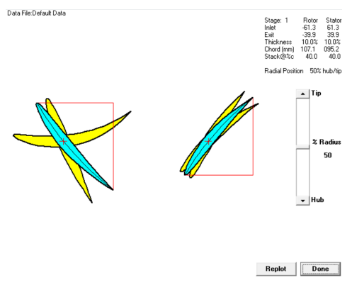
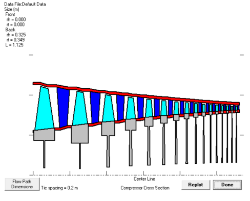
Compressor:
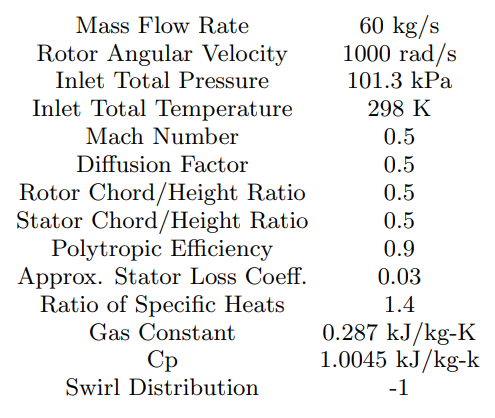
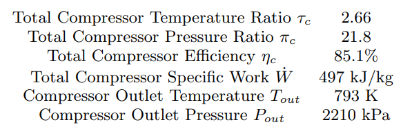
- In the compressor design section of this project, the primary objective is to maximize the total compressor ratio while considering exit temperature and total compressor efficiency.
- Parameters like solidity, inlet angle (α1), and number of stages significantly impact pressure and temperature behaviors:
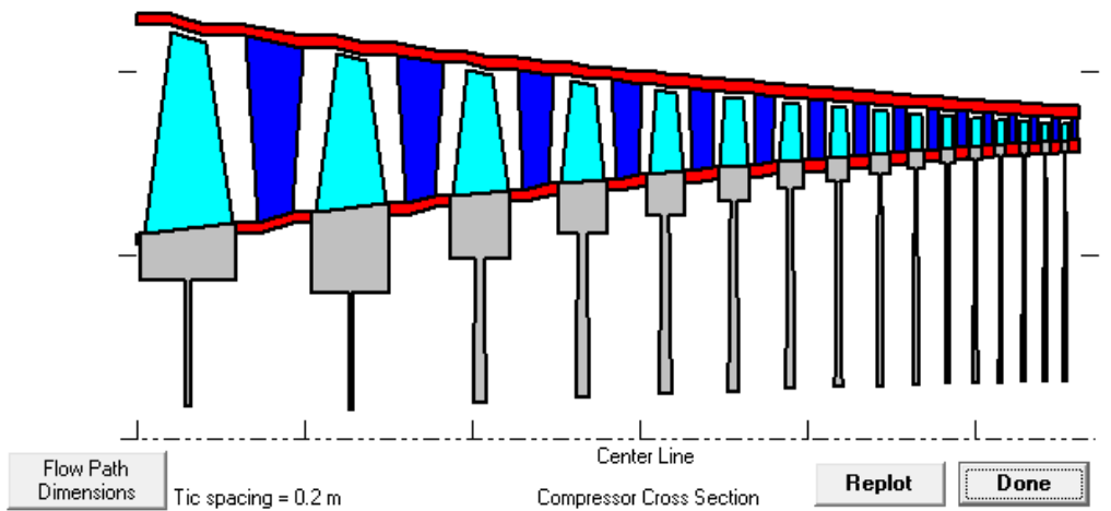
- COMPR Program:
- The analysis was conducted using the COMPR program, which allows for variation of parameters such as number of stages, inlet angle (α1), and solidity to explore their effects on compressor performance metrics like pressure ratio, temperature ratio, and efficiency.
- Equations and Parameters:
- Total Compressor Efficiency (ηtotal): \( \frac{W_{actual}}{W_{isentropic}} \)
- Specific Work (W): \( \frac{h_{exit} - h_{inlet}}{\eta_{total}} \)
- Outlet Temperature (Texit) and Pressure (Pexit) behaviors.
- Key Findings and Analysis:
- Relationship between compressor pressure ratio and solidity: As solidity increases, pressure ratio also increases.
- Relationship between compressor temperature ratio and solidity: Increasing solidity leads to higher temperature ratios, affecting efficiency and thermal management.
- Effect of inlet angle (α1) on pressure and temperature ratios: Higher inlet angles correlate with increased pressure and temperature ratios.
- Influence of number of stages on pressure and temperature ratios: Increasing stages generally improves pressure ratio but may increase temperature ratio, impacting thermal loads and efficiency.
- Impact of number of stages on compressor efficiency: Efficiency tends to decrease as the number of stages increases, indicating potential design or operational considerations for optimization.
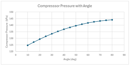 Compressor Pressure with Angle
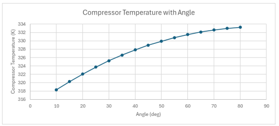 Compressor Temperature with Angle
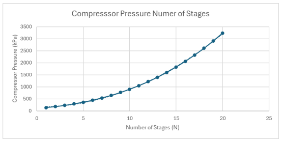 Compressor Pressure with stages
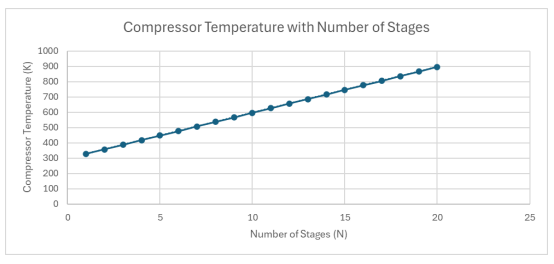 Compressor Temperature with Number of Stages
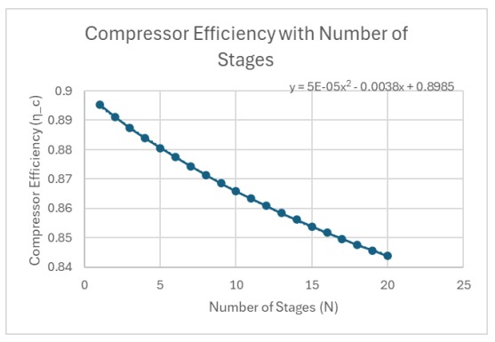 Compressor Efficiency with Number of Stages
 CHAMBER.png)
 THROAT.png)
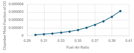
Combustor:
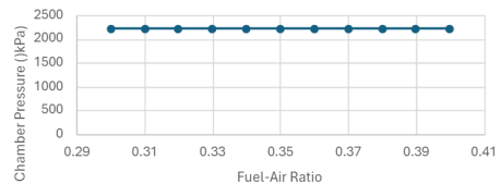
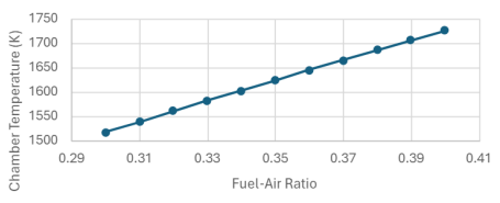
The heart of the engine, the combustor, transforms fuel and air into high-temperature gases. Analysis involves selecting fuel type, combustion strategy, and equivalence ratio while maintaining temperature constraints. Plots depict temperature profiles, emissions levels, and pressure variations.
CEARUN Program:- The CEARUN program provides a graphical user interface for engineers to create and analyze combustion plots.
- The program allows for the selection of fuel type, combustion strategy, and equivalence ratio.
- Temperature profiles, emissions levels, and pressure variations are displayed.
- The choice of Jet-A(L) fuel was based on its availability, energy density, safety, and industry standardization. A fuel-lean approach with a ratio of 0.39 was selected to maximize efficiency and minimize emissions.
- Fuel Requirements: A fuel-air mix between 0.3 and 0.4 ensures efficient combustion and minimal emissions.
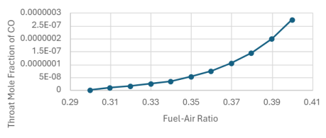
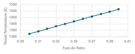
- Exit Temperature: The combustor exit temperature was found to be 1494 K, close to the maximum limit of 1500 K.
- Exhaust Emissions: The mole fractions of CO and NO were determined to be \(2.00 \times 10^{-7}\) and \(9.00 \times 10^{-4}\) respectively.
\( \text{Mole Fraction of CO} = 2.00 \times 10^{-7} \)
\( \text{Mole Fraction of NO} = 9.00 \times 10^{-4} \)
Key Findings and Analysis:- Fuel Type and Combustion Strategy: The choice of fuel type and combustion strategy impacts efficiency, temperature distribution, and emissions.
- Fuel-Air Ratio: The fuel-air ratio varied from 0.1 to 2.0 with increments of 0.1, and from 0.30 to 0.40 with increments of 0.01. The optimal ratio was found to be between 0.3 and 0.4.
- Combustor Inlet Conditions: The compressor performance affects combustor inlet temperature and pressure.
- Temperature Ratio: Increasing the fuel-air ratio leads to a rise in temperature ratio. Optimal fuel-air ratio is between 0.3 and 0.4 to maximize the temperature ratio while keeping the throat temperature under 1500 K.
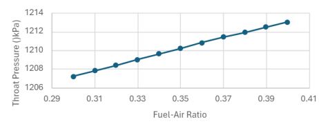
- Pressure Variations: Chamber and throat pressure ratios vary with the fuel-air ratio, providing insights into pressure changes within the combustor.
- Emissions Levels: Lower fuel-air ratios are associated with smaller CO and NO emissions.
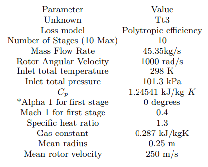
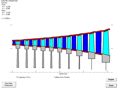
Turbine
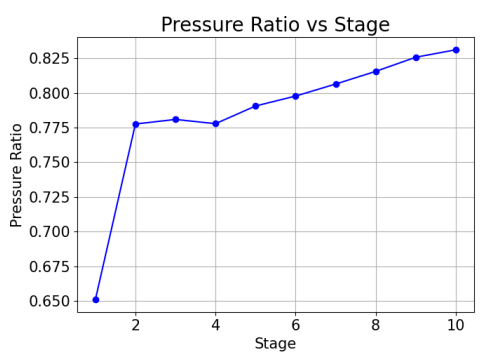
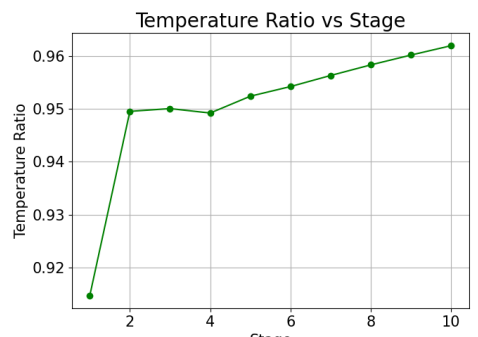
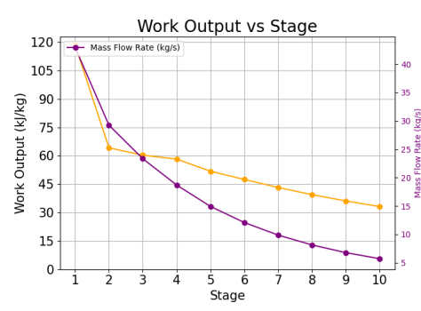
Efficient operation, cost minimization, and compressor-turbine matching are focal points in turbine design. Plots illustrate pressure, temperature, efficiency, work output, and mass flow rate across turbine stages. Considerations include work output, turbine efficiency, and mass flow rate calculations to ensure optimal turbine performance.
CEARUN Program- Analysis of total turbine work output to determine the necessary number of turbine stages for driving the compressor efficiently.
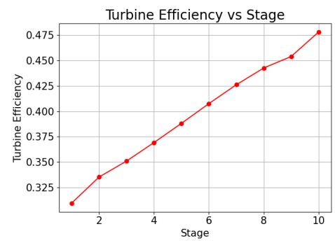
- Calculation of turbine efficiency using data from the TURBN program, with observed efficiencies ranging from 90.22% to 90.44%.
- Observation of mass flow rate through the turbine, indicating a decrease from 60 kg/s at the compressor to 45 kg/s at the turbine, suggesting efficient energy conversion.
- Work output (\(W_{\text{out}}\)) is determined by the change in enthalpy (\(\Delta h\)) of the working fluid:
\(W_{\text{out}} = C_p \times (T_{t1} - T_{t3})\)
- Total temperature ratio (\(T_{\text{tratio}}\)) represents the ratio of outlet to inlet temperature:
\(T_{\text{tratio}} = \frac{T_{\text{outlet}}}{T_{\text{inlet}}}\)
- Total pressure ratio (\(P_{\text{tratio}}\)) shows the ratio of outlet to inlet pressure:
\(P_{\text{tratio}} = \frac{P_{\text{outlet}}}{P_{\text{inlet}}}\)
- Turbine efficiency (\(\eta_{\text{turbine}}\)) is the ratio of actual work output to the ideal work output:
\(\eta_{\text{turbine}} = \frac{C_p \times (T_{t1} - T_{t3})}{R \times T_{\text{inlet}} \times \left(\frac{P_{t1}}{P_{t3}}\right)}\)
- Turbine outlet temperature (\(T_{t\text{outlet}}\)) is calculated as:
\(T_{t\text{outlet}} = T_{t1} - (T_{t1} - T_{t3}) \times \left(\frac{P_{t1}}{P_{t3}}\right)\)
- Turbine outlet pressure (\(P_{t\text{outlet}}\)) is calculated as:
\(P_{t\text{outlet}} = P_{03} \times \left(\frac{P_{04}}{P_{03}}\right)\)
- Mass flow rate (\(\dot{m}\)) through the turbine:
\(\dot{m} = M_1 \times \frac{P_{t1}}{R \times T_{t1}} \times \sqrt{C_p \times R \times T_{t1}}\)
- The turbine stages consistently show high efficiency, ranging from 90.22% to 90.44%.
- Mass flow, temperature, and pressure increase through the stages, indicating effective energy addition to the fluid.
- Steady velocity ratio of 1.0000 is maintained through adjustments in vane and blade counts.
- Pressure ratio (Pt3/Pt1) and temperature ratio (Tt3/Tt1) increase as the fluid moves through the turbine stages.
- Efficiency trends across different turbine stages show increasing efficiency with values between 90.22% and 90.44%.
- Work output decreases as the fluid moves through the turbine, with a mass flow rate decreasing from 60 kg/s at the compressor to 45 kg/s at the turbine.
Aeroengine Design Project Conclusion:
The project provides insights into gas turbine engine core design and analysis, addressing specific requirements and constraints. Leveraging analytical tools and thorough evaluations, the project aims to enhance engine efficiency, performance, and cost-effectiveness.