NovaTech Space Systems: Rocket Design

Summary:
- Rocket Design Mentor: Dr. Justin Little
- Rocket Design Team: Felicity Cundiff, Grayson Atwell, Mack Rowan Howard, Andrew Truong, Kai Alden Laslett-Vigil, and Daniel Molidor
- 1. NovaTech Rocket Prop Presentation: Here
- 2. NovaTech Rocket Prop Report: Here
A group of venture capitalists expressed interest in funding a network of small satellites to provide satellite internet coverage globally. They tasked our team with designing a low-cost rocket featuring a reusable first stage capable of deploying a single 1,000 kg satellite into a 500 km altitude low-Earth orbit (LEO). Key design requirements included delivering the payload efficiently, minimizing costs, and ensuring reusability of the first stage.
-
NOVA 1 rocket project:
- Initiated in response to venture capitalists' challenge for a cost-effective LEO satellite deployment solution.
- Focuses on designing a gas turbine engine core for airbreathing propulsion with emphasis on efficiency and turbine inlet temperatures.
- Engine components (compressor, combustor, turbine) crucial for engine efficiency and emissions control.
- Design decisions prioritize efficiency, cost-effectiveness, and performance at designated design points.
- Engineered to deliver a 1,000 kg payload to a 500 km Low Earth Orbit (LEO) with a ∆V budget of 9 km/s.
- Boasts a launch cost of $13.5 million per launch, demonstrating cost-effectiveness.
- Performance attributes include a launch mass of 15,266 kg, ∆V of 9.175 km/s, burnout altitude of 545 km, and burn time of 439.6 seconds.
-
To ensure optimal performance and minimize propellant loss:
- The NOVA 1 employs a sophisticated cryogenic fuel storage system.
- Double-walled vacuum storage tanks made from stainless steel and carbon steel house liquid hydrogen and oxygen.
- Designed to mitigate boil-off a nd maintain propellant integrity throughout the mission, drawing inspiration from NASA's Kennedy Space Center practices.
-
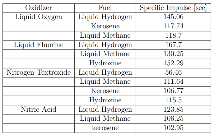
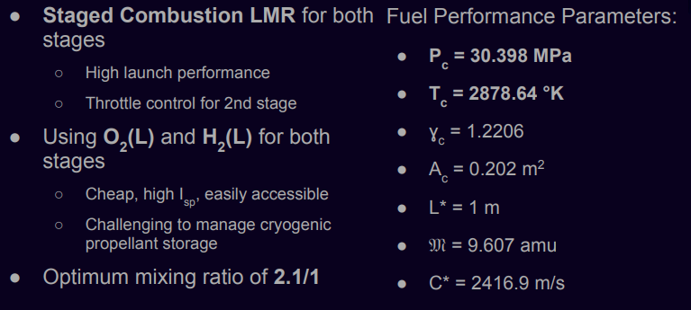
Staged Combustion Liquid Rocket Motors (LMR) using Oxygen (O2) and Hydrogen (H2):
- - Chosen for both stages due to their cost-effectiveness and high specific impulse (Isp).
-
A meticulous technical approach guided the NOVA 1 project:
-
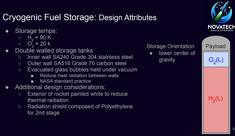
Storage Temperatures:
- - Liquid Hydrogen: Stored at 20◦K for optimal performance and stability.
- - Liquid Oxygen: Stored at 90◦K to maintain its liquid state during storage and operation.
-
Storage System Design:
- - Utilizes a double-walled vacuum system for cryogenic propellants.
- - Inner wall: Constructed from SA240 Grade 304 stainless steel for structural integrity and corrosion resistance.
- - Vacuum between walls filled with evacuated glass bubbles under mild vacuum to minimize heat transfer via radiation.
- - Outer wall: Made of SA516 Grade 70 carbon steel, primarily serving as an insulating layer to reduce heat ingress.
-
Inspiration and Additional Design Considerations:
- - Draws design inspiration from NASA Kennedy Space Center's proven large-scale hydrogen storage tanks.
- - Exterior of the rocket body painted white to reflect solar radiation and reduce absorption, crucial for missions launched from equatorial regions.
- - Second stage incorporates a polyethylene radiation shield to further mitigate the effects of solar radiation beyond the atmosphere.
-
Tank Orientation and Specifications:
- - Tanks in both stages oriented with the Oxygen tank above the Hydrogen tank to lower the rocket's center of gravity as propellants are consumed.
- - All storage tanks designed cylindrically with an inner radius of 2 meters for structural efficiency and uniform distribution of propellants.
- - First stage: Holds 6469.56 kg of Hydrogen and 3080.742 kg of Oxygen.
- - Second stage: Contains 1744.829 kg of Hydrogen and 830.871 kg of Oxygen.
- - Total estimated height of the propellant tanks reaches 9.5 meters, optimizing volume and space efficiency within the rocket design.
-
-
Integral to the rocket's propulsion system:
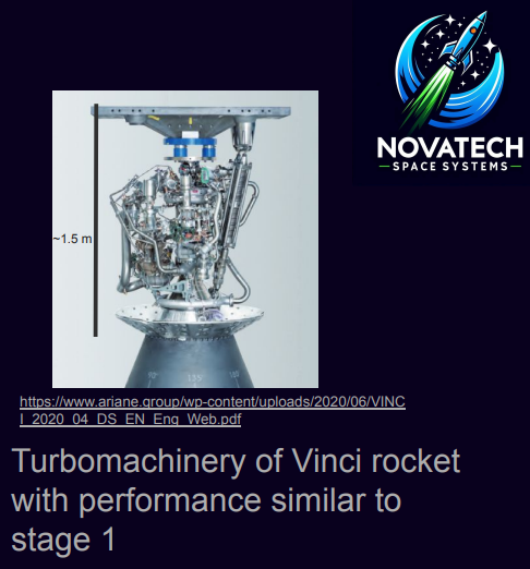
- - Turbomachinery efficiently delivers propellants to the combustion chamber.
- - Staged combustion LRMs ensure precise fuel delivery and combustion efficiency.
-
Process of Sizing and Optimizing Turbopumps:
-
We began by calculating the exit pressures of the fuel and oxidizer. The exit pressure of the fuel \( P_{fe} \) and the oxidizer \( P_{oxe} \) were determined using the following equations:
- \( P_{fe} = (1 + 0.82)P_c \), where \( P_c \) is the chamber pressure set to 300 atm, yielding \( P_{fe} = 546 \, \text{atm} \).
- \( P_{oxe} = (1 + 0.12)P_c \), yielding \( P_{oxe} = 336 \, \text{atm} \).
-
Next, the pressure of the gas generator combustion chamber \( P_{cgg} \) was estimated using the minimum pressure from the oxidizer exit pressure:
- \( P_{cgg} = \frac{P_{oxe}}{1.02} \), yielding \( P_{cgg} = 329.4 \, \text{atm} \).
-
We then estimated the turbine exit pressure \( P_{t,e} \) using the ambient pressure \( P_a \) and the specific heat ratio \( \gamma_{gg} \) of the gas generator, which was calculated as follows:
- \( P_{t,e} = P_a \left( \frac{\gamma_{gg} + 1}{2} \right)^{\frac{\gamma_{gg}}{\gamma_{gg} - 1}} \), yielding \( P_{t,e} = 1.84 \, \text{atm} \).
-
To determine the power required for the turbopump's turbine, we used the equation for turbine power, incorporating the mass flow rate \( \dot{m}_{gg} \), turbine efficiency \( \eta_t \), specific heat at constant pressure \( C_{p,gg} \), and the gas generator combustion chamber temperature \( T_{cgg} \).
- \( \text{Turbine Power} = \dot{m}_{gg} \eta_t C_{p,gg} T_{cgg} \left[ 1 - \left( \frac{P_{t,e}}{P_{cgg}} \right)^{\frac{\gamma_{gg} - 1}{\gamma_{gg}}} \right] \)
-
We then solved for the unknown mass flow rate of the gas generator \( \dot{m}_{gg} \) using the following equation, which relates the power required by the turbopump to the pressure drops and densities of the propellants:
- \( \text{Turbine Power} = \left( \dot{m}_f + \frac{\dot{m}_{gg}}{1 + r_{gg}} \right) \frac{\Delta P_f}{\rho_f \eta_{pf}} + \left( \dot{m}_{ox} + \frac{r_{gg} \dot{m}_{gg}}{1 + r_{gg}} \right) \frac{\Delta P_{ox}}{\rho_{ox} \eta_{pox}} \)
where \( \Delta P_f \) and \( \Delta P_{ox} \) are the pressure increases for the fuel and oxidizer, and \( \rho_f \) and \( \rho_{ox} \) are their respective densities.
-
The results for the mass flow rates of the gas generator were found to be:
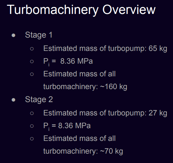
- \( \dot{m}_{gg1} = 5.035 \, \text{kg/s} \) for stage 1
- \( \dot{m}_{gg2} = 1.255 \, \text{kg/s} \) for stage 2
-
The power required for the turbopumps was calculated as follows:
- First stage: \( 21198 \, \text{kW} \)
- Second stage: \( 5283.7 \, \text{kW} \)
-
We estimated the torque for each stage using the equation:
- \( \tau = \frac{\text{Turbine Power}}{\omega} \), where \( \omega = 50000 \, \text{rad/s} \).
- First stage torque: \( 423.96 \, \text{N} \cdot \text{m} \) (312.69 ft*lbs)
- Second stage torque: \( 105.67 \, \text{N} \cdot \text{m} \) (77.940 ft*lbs)
-
Finally, the weight of the turbopumps was calculated using the torque values:
- \( W = 5.26 \tau^{0.638} \)
- First stage: 205.5 lbs (93.21 kg)
- Second stage: 84.71 lbs (38.42 kg)
-
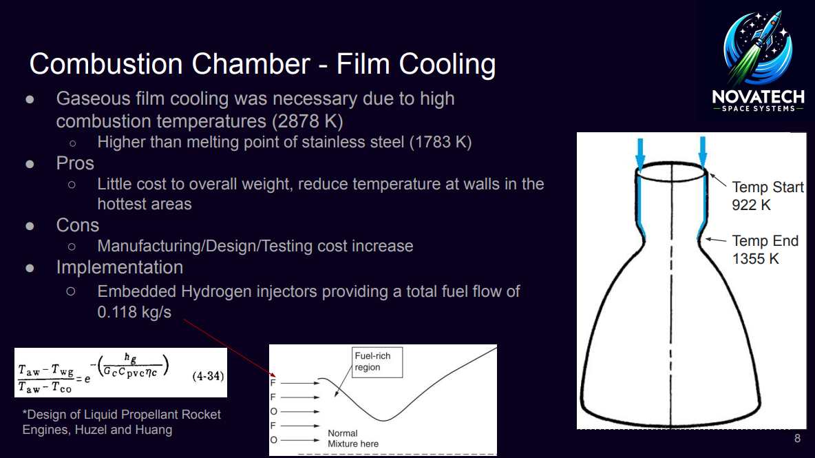
- - To manage the high combustion chamber temperatures (2878 K) and prevent melting the stainless steel combustion chamber (1783 K), gaseous film cooling is implemented in the design.
- - Hydrogen supplied by the turbine is used for this task along with the outer parameter of injectors being fuel only.
- - The starting temperature of this fluid is 922 K and enough flow rate of hydrogen will keep it to a maximum of 1355 K up to the throat section. 1355 K was chosen for margin of safety and integrity of the steel.
- - The theoretical equation from Hatch and Papell is used to find out the film coolant weight flow rate per unit area:
\[ \frac{{(T_c - T_{wg})}}{{(T_c - T_{co})}} = e^{-\left(\frac{{h_g}}{{G_c \cdot C_{p,v}}}\right) \cdot \eta_c} \] - This equation is then used to calculate 0.118 kg/s of extra fuel during flight to maintain ideal temperatures of the wall temperature. Due to both stages being similar, this applies to both stages.
- Cooling Selection: We chose a single-pass regenerative cooling system for our rocket, considering initial parameters such as pressure, mass, chamber conditions, and cooling system specifics (equivalent diameter, channel dimensions, wall thickness, and fuel flow rate).
- Coolant Jacket: The number of cooling channels (N) and mass flow rate per channel (\( \dot{m}_{chan} \)) were determined:
\( \dot{m}_{chan} = \frac{1}{N} \cdot mf \)
\( N = \frac{\pi}{\sqrt{De} + 0.8(d + 2tw)} \) (Eq. 14) - Heat Transfer: Heat transfer management is critical for optimal performance and preventing thermal damage. Thermal energy exchange between gas and wall surfaces is represented by:
\( q' = hg \cdot (Tr - TW_g) \) (Eq. 15) - Gas-side wall temperature (TW_g) stabilized at 2602.4952 K after 9 iterations. The convective heat transfer coefficient (hg) was iteratively calculated using Newton-Raphson method and Nusselt number, with liquid-side wall temperature (TW_l) stabilizing at 2501.7347 K after 2 iterations:
\( Nu = 0.023 \times (Pr^{0.3}) \times (M^{0.33}) \)
\( hg = Nu \cdot \frac{kgas}{De} \) (Eq. 16) - Exploration of controlled reentry and landing capabilities for the first stage, utilizing excess ΔV to enhance reusability.
- Optimization of the first stage design, including pressure matching to sea level conditions and implementation of stability control mechanisms such as fins or gimbling nozzles.
- Structural analysis of the combustion chamber and storage tanks to determine optimal wall thickness for containing high pressures.
- Exploring the use of passive cooling techniques in the nozzle design to reduce manufacturing and operational costs.
Introduction and Background:
Technical Approach:
Fuel Choice:
Cryogenic Fuel Storage:
Turbomachinery:
Combustor - Film Cooling:
Regenerative Cooling
Regenerative cooling system Code:
    clc
    clear
    close all

    % Rocket parameters
    P_i = 303.98 * 10^5; % Initial pressure [Pa]
    M = 9.607 * 1.66054e-27; % Mass of H2 molecule [kg]
    Pc = 303.98 * 10^5; % Chamber pressure [Pa]
    Ve = 2374.5; % Exit velocity [m/s]
    Pe = 0.33994 * 10^5; % Exit pressure [Pa]
    C = 4314.1; % Speed of sound [m/s]
    Tc = 2878.64; % Chamber temperature [K]
    C_star = 2416.9; % Characteristic velocity [m/s]
    CF = 1.785; % Thrust coefficient
    gamma_c = 1.2206; % Specific heat ratio
    At = 0.00373;

    % Regenerative cooling system parameters
    De = 0.0933; % Equivalent diameter [m]
    d = 0.0212; % Channel diameter [m]
    tw = 0.00373; % Channel wall thickness [m]
    mf = 44.48; % Fuel mass flow rate [kg/s]

    % Step 1: Calculate N and mchan
    N = (pi^(1/2)*De + 0.8*(d + 2*tw)) / (d + 2*tw);
    mchan = mf / N;

    % Step 2: Initialize i
    i = 1;

    % Step 3: Begin stepping down tube/channel
    i = i + 1;

    % Step 4: Guess the wall temperature on gas side, Twgi.
    tolerance = 1e-6; % Tolerance for convergence
    max_iterations = 100; % Maximum number of iterations
    % Initial guess for Twgi
    Twgi_guess = 300; % Initial guess for Twgi [K]
    % Iterative loop to guess Twgi
    for iteration = 1:max_iterations
        % Calculate functions f(Twgi) and its derivative
        [f_Twgi, df_Twgi] = calculate_functions(Twgi_guess);
        % Twgi using Newton-Raphson method
        Twgi_new = Twgi_guess - f_Twgi / df_Twgi;
        % Check convergence
        if abs(Twgi_new - Twgi_guess) < tolerance
            Twgi = Twgi_new;
            fprintf('Twgi converged after %d iterations.\n', iteration);
            break;
        end
        % Update guess for next iteration
        Twgi_guess = Twgi_new;
        % Check for maximum iterations reached
        if iteration == max_iterations
            warning('Maximum iterations for Twgi reached without convergence.');
        end
    end

    % Step 5: Calculate hg then q' = hg * (Tr - Twgi)
    T_chamber = Tc; % Chamber temperature [K]
    p_chamber = Pc; % Chamber pressure [Pa]
    Pr = 0.7; % Prandtl number
    Nu = 0.023 * (Pr^0.3) * (M^0.33); % Nusselt number
    k_gas = 0.03; % Thermal conductivity of gas [W/(m*K)]
    % Calculate hg using correlation
    hg = Nu * k_gas / De; % Convective heat transfer coefficient [W/(m^2*K)]
    % Calculate heat transfer rate q'
    Tr = T_chamber; % Temperature of the gas [K]
    q_prime = hg * (Tr - Twgi); % Heat transfer rate [W/m^2]

    % Step 6: Calculate Twli from conduction through the wall, q = k * (Twgi - Twli) / tw
    % Thermal conductivity of the wall material [W/(m*K)]
    k_wall = 25; % Example value, replace with actual value for your material
    % Initial guess for Twli
    Twli_guess = 2500; % Example guess, replace with appropriate initial guess
    % Define convergence criteria
    tolerance_twli = 1e-6; % Tolerance for convergence
    max_iterations_twli = 1000; % Maximum number of iterations
    % Iterative loop to calculate Twli
    for iteration_twli = 1:max_iterations_twli
        % Calculate q from the previous step (Step 5)
        q_wall = q_prime; % Heat transfer rate through the wall [W/m^2]
        % Calculate Twli using conduction equation
        Twli_new = Twgi - q_wall * tw / k_wall;
        % Check convergence
        if abs(Twli_new - Twli_guess) < tolerance_twli
            Twli = Twli_new;
            fprintf('Twli converged after %d iterations.\n', iteration_twli);
            break;
        end
        % Update guess for next iteration
        Twli_guess = Twli_new;
        % Check for maximum iterations reached
        if iteration_twli == max_iterations_twli
            warning('Maximum iterations for Twli reached without convergence.');
        end
    end

    % Step 7: Compute hl based on Tl(i-1) (temperature in previous segment)
    T_l_previous = 400; % Temperature in previous segment [K]
    Pr_l = 0.7; % Prandtl number for the liquid
    Nu_l = 0.023 * (Pr_l^0.3); % Nusselt number for the liquid
    k_l = 0.6; % Thermal conductivity of the liquid [W/(m*K)]
    % Calculate hl using correlation
    hl = Nu_l * k_l / De; % Convective heat transfer coefficient for the liquid [W/(m^2*K)]

    % Display hl
    fprintf('Convective heat transfer coefficient for the liquid (hl): %.4f W/(m^2*K)\n', hl);
    % Define an initial value for Tl_current
    Tl_current = 300;

    % Step 10: Obtain a new liquid temperature in the ith segment
    rho_l = 800; % Liquid density [kg/m^3]
    mu_l = 0.0003; % Liquid viscosity [Pa*s]
    q_dAi = 100; % Example value [W/m^2]
    bi = 0.05; % Example value [m]
    Delta_Si = 0.1; % Example value [m]
    Pl_current = 1.0e5; % Example value [Pa]
    di = 0.01; % Example value [m]
    % Provided values for xi_next and xi_current
    xi_next = 2;
    xi_current = 1;
    % Calculate new liquid temperature Tl(i+1) based on the given formula
    Delta_xi = xi_next - xi_current;
    Tl_new = Tl_current + (1 / (mchan * Delta_xi)) * (q_dAi * bi * Delta_Si) + 2000;
    % Update liquid properties based on the new temperature Tl_new
    Re = mchan / (rho_l * At); % Reynolds number
    if Re < 2100
        cfi = 16 / Re;
    elseif Re >= 5000 && Re <= 200000
        cfi = 0.046 / Re^0.2;
    elseif Re > 3000 && Re <= 3000000
        cfi = 0.0014 + 0.125 / Re^0.32;
    end
    v_l = mchan / (rho_l * At); % Liquid velocity
    target_pl = 296.2; % Desired liquid pressure
    Pl_new = Pl_current - cfi * (Delta_xi / di) * (2 * rho_l * v_l^2);
    pressure_difference = Pl_new - target_pl;
    Pl_new_adjusted = Pl_new - pressure_difference;

    % Step 11: Move onto the next segment or manifold % Define the total number of segments in the jacket
    num_segments_in_jacket = 10;
    % Define reached_end_of_jacket_or_manifold condition based on your problem's requirements
    % For example, you might have a condition to check if the current segment is the last one in the jacket:
    reached_end_of_jacket_or_manifold = (i == num_segments_in_jacket);
    % Check if we have reached the end of the jacket or at intermediate manifolds
    if reached_end_of_jacket_or_manifold
        % Set manifold pressure equivalent to the local static pressure of the last segment
        manifold_pressure = local_static_pressure_of_last_segment;
        % Reset for the next segment or manifold
        % You may need to reset variables, indices, etc., depending on your implementation
        % Example:
        i = i + 1; % Move onto the next segment
        Twgi_guess = initial_guess_for_Twgi; % Reset the initial guess for Twgi
        % Reset other variables as needed
    else
        % Continue to the next segment
        i = i + 1;
    end

    % Display new liquid temperature and pressure
    fprintf('New liquid temperature (Tl(i+1)): %.4f K\n', Tl_new);
    fprintf('New liquid pressure (Pl(i+1)): %.4f Pa\n', Pl_new_adjusted);

    % Function to calculate functions f(Twgi) and its derivative
    function [f_Twgi, df_Twgi] = calculate_functions(Twgi)
        % You need to define these functions based on your system equations
        % This is just a placeholder
        f_Twgi = Twgi^2 - 100;
        df_Twgi = 2 * Twgi;
    end